
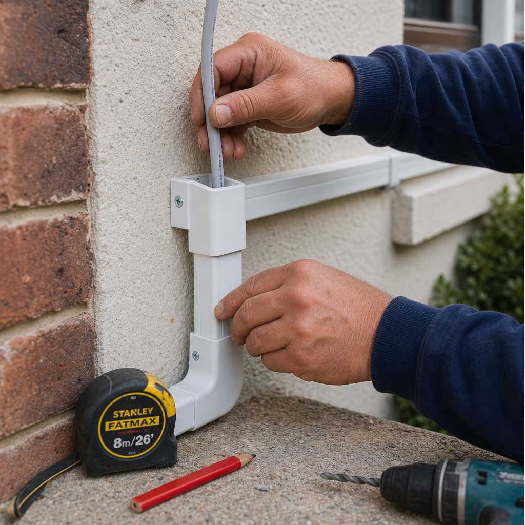
Most property managers and homeowners who attempt a video door entry installation without preparation end up with a system that buzzes but never connects, or a door station wiring mess that trips the breaker on day one. The process is not as complicated as installers would like you to believe, but it does require following a specific sequence. Skip one step and the whole system fails. This guide walks through every stage from site assessment to final commissioning, using real-world details that come from working with door entry systems across apartments, offices, and gated properties.
Table of Contents
- Quick Takeaways
- Tools and Materials You Need Before You Start
- Understanding System Types: Wired vs. Wireless Video Intercom
- Site Assessment and Planning
- Door Station Wiring: The Step Everyone Gets Wrong
- Mounting the Door Station
- Connecting the Indoor Monitor or App
- Integrating Access Control: Locks, Relays, and Gate Systems
- Comparing Installation Approaches
- Testing and Commissioning the System
- Frequently Asked Questions
- References
Quick Takeaways
| Key Insight | Explanation |
|---|---|
| Plan cable runs before drilling anything | Mapping your cable route on paper first prevents costly mistakes in masonry, drywall, or conduit that cannot be easily reversed. |
| Use shielded twisted-pair cable for door station wiring | Unshielded cable picks up electrical interference and degrades audio and video quality, especially in runs over 15 meters. |
| Match power supply voltage exactly | Most door station units require 12V DC or 24V AC. Using the wrong supply destroys the camera module and voids the warranty. |
| Wireless systems need a strong Wi-Fi signal at the door | A signal below -70 dBm at the outdoor unit causes dropped calls and freeze-frames during visitor identification. |
| Test the door release relay before sealing the wall | Confirming the relay triggers the electric strike or magnetic lock before closing up the wall saves hours of rework. |
| Weatherproofing the door station is non-negotiable | Outdoor-rated enclosures with IP65 or higher ratings prevent moisture damage that is the number-one cause of premature failure in door entry cameras. |
| Label every wire at both ends immediately | Unlabeled wires in a multi-unit building become a troubleshooting nightmare within six months. Label during installation, not after. |
Tools and Materials You Need Before You Start

Walking up to the job with just a screwdriver is a guaranteed way to make two trips to the hardware store. Before starting a video door entry installation, gather every item on this list so the work stays continuous.
You will need a power drill with masonry and wood bits, a cable fish tape or rod set, wire strippers, a voltage tester, a small flat-head and Phillips screwdriver set, a spirit level, and a label maker. For materials: the video intercom unit itself (door station plus indoor monitor or app-connected hub), the correct cable type for your run distance, conduit or cable clips, a compatible power supply, terminal block connectors, and weatherproof sealant for exterior penetrations.
A common mistake is buying a door station and indoor monitor from different brands hoping they will be compatible. They rarely are unless you are using a system built on the SIP protocol or a vendor that explicitly publishes third-party compatibility. Products from UnikCCTV’s video door entry range are matched and tested as complete systems, which eliminates the guessing.
Pro tip: Buy 15 percent more cable than your measured run length. Walls, corners, and conduit bends consume more cable than flat measurements suggest, and running short forces a splice that degrades signal quality.
Understanding System Types: Wired vs. Wireless Video Intercom
The choice between a wired and wireless system shapes every other decision in this guide, including which cable to buy, how to plan your power supply, and how to handle multi-unit access.
Wired Video Intercom Systems
Wired systems use a dedicated cable, typically 2-wire or 4-wire configurations depending on the manufacturer, to carry both power and signal between the door station and the indoor monitor. They are more reliable over long runs, perform better in electrically noisy environments like parking garages, and are the correct choice for buildings with more than four entry points.
The trade-off is installation complexity. Running cable through finished walls and ceilings in an existing building takes considerably more time than a new construction rough-in. In practice, wired systems in apartment buildings require planning cable routes through conduit from the entry panel to each unit’s indoor monitor, which is a project that benefits from a structured cabling layout drawn up in advance.
Wireless and App-Based Video Intercom Systems
Wireless systems, including Wi-Fi-based and those using proprietary RF protocols, reduce physical cabling to a power feed at the door station only. The communication between door station and resident happens over the network or via a cloud server to a smartphone app. This is the fastest installation path for single-family homes and small commercial properties.
The honest limitation: wireless systems depend entirely on network stability. A router reboot, ISP outage, or weak Wi-Fi signal at the front door renders the system non-functional. For mission-critical access control on a commercial property, a wired backbone with wireless extensions is a more defensible design than a fully wireless system.
Site Assessment and Planning
A site assessment done right takes 30 to 45 minutes and prevents three to four hours of rework. Start at the door station mounting location and work backward to the indoor monitor position or network equipment location.
Measuring and Mapping Cable Routes
Measure the total cable run from the outdoor door station to the indoor monitor, adding vertical drops and horizontal runs through walls. For runs exceeding 50 meters on a standard 2-wire system, check the manufacturer’s maximum run specification. Some systems using unshielded cable degrade visibly beyond 30 meters. Shielded twisted-pair (STP) cable handles longer distances with less signal loss and is worth the small additional cost on any run over 15 meters.
Identify where the cable will penetrate the exterior wall and how it will be protected from water ingress. A common mistake is running cable through an unsealed hole in a masonry wall, which creates a moisture path that corrodes the terminal connections at the door station within two to three years in wet climates.
Power Supply Location and Capacity
Determine where the power supply unit will be mounted. It needs to be within reach of a mains power outlet or a dedicated circuit. If the system includes a door release (electric strike or electromagnetic lock), calculate the combined current draw of the door station and the lock to ensure the power supply is adequately rated. Under-speccing the power supply by even 20 percent causes voltage drops that corrupt the video feed and cause the door release to chatter instead of holding open cleanly.
“The most common installation failure we see is a power supply that is technically functional but chronically under-loaded for the system it is meant to drive. Voltage drops of even 1V on a 12V DC system cause video noise and unreliable door release behavior.” – Field observation from access control installation professionals, echoed consistently in technical support cases across the industry.
Door Station Wiring: The Step Everyone Gets Wrong
Door station wiring is where most DIY installations fail. The terminal block on the back of a door station typically has between four and eight terminals, and the labeling on budget units is sometimes printed in a font small enough to require a magnifying glass. Getting this wrong means either no power, no audio, no video, or a door release that fires continuously.
Standard 4-Wire Wired System Connections
In a standard 4-wire video intercom installation, the wires are typically assigned as follows: two wires carry power (positive and negative from the power supply), one wire carries the video signal, and one wire carries the audio signal. Some manufacturers combine video and audio on a single coax-style conductor, with the remaining two wires handling power. Always verify against the specific wiring diagram supplied with your unit.
Strip each wire back 8mm, no more. Excess bare conductor inside the terminal block increases the risk of an unintended short between adjacent terminals. Tighten each terminal screw firmly. A loose connection on the power terminal causes intermittent system resets that are genuinely difficult to diagnose after installation.
2-Wire Bus System Connections
Modern 2-wire bus systems from brands stocked at UnikCCTV’s intercom systems collection transmit power, audio, video, and control signals on just two conductors using digital encoding. This makes installation faster because polarity is often not required. However, the bus termination resistors must be set correctly at the first and last device on the bus. Skipping this step causes signal reflections that manifest as audio echo or video tearing on the indoor monitor.

Pro tip: Photograph the back of the door station terminal block with your phone before attaching any wires. If you need to troubleshoot later, you have a clean reference of the terminal layout that is far easier to read than the manual.
Mounting the Door Station
The door station camera angle is fixed after installation, so mounting height and horizontal positioning determine how useful the image actually is. The standard mounting height for a door station with a wide-angle lens is 1.5 meters (approximately 60 inches) from the ground to the center of the unit. This places a standing adult’s face in the center of the frame at a typical interaction distance of 0.5 to 1 meter.
For properties with gate access or vehicle entry, the camera angle needs to cover both a driver at the gate intercom and approaching pedestrians. In that scenario, a door station with a wider field of view (120 degrees or more) mounted at 1.2 meters captures both use cases without requiring two separate cameras.
Flush Mount vs. Surface Mount
Flush mounting requires cutting a precise recess into the wall or gate column and is the cleaner finish for high-end residential and commercial installations. Surface mounting using the supplied backbox is faster, fully reversible, and perfectly appropriate for the majority of installations. If the wall surface is uneven (brick, rough concrete), use a surface mount backbox and apply weatherproof sealant around the perimeter after the unit is secured.
Use a spirit level on every installation. A visibly tilted door station looks unprofessional and slightly misaligns the camera’s field of view from the intended center point, which matters more than most installers acknowledge.
Connecting the Indoor Monitor or App
Indoor monitor connection depends on your system type. For wired systems, the monitor typically mounts on an interior wall near the entry or in a central living area, powered either by the system cable or by a local 12V DC adapter. Terminate the wires at the monitor’s terminal block following the same labeling conventions as the door station, matching audio, video, and power terminals exactly.
For app-based systems, the indoor monitor is replaced by a router-connected hub or by a direct Wi-Fi connection from the door station to the resident’s smartphone. After powering the door station, connect it to the property’s Wi-Fi network using the manufacturer’s setup process, which typically involves scanning a QR code or pressing a pairing button. Assign the device a static IP address in the router settings to prevent the system going offline if the router reassigns addresses after a reboot.
Multi-Unit Apartment Configurations
In a multi-unit building, each apartment requires its own indoor monitor wired back to the door station on the bus. Each monitor is assigned a unique address using DIP switches or a software menu. The door station directory must be programmed to map each apartment number to the correct monitor address. This programming step is skipped surprisingly often, resulting in calls that ring to the wrong unit or not at all.
Integrating Access Control: Locks, Relays, and Gate Systems
A video door entry system without a door release is a video intercom. The access control integration is what makes it a complete entry system. Most door stations include a built-in dry contact relay that can trigger an electric strike, electromagnetic lock, or gate controller when the resident presses the door open button on the indoor monitor or app.
Electric Strike Wiring
An electric strike is normally held in a locked position and unlocks when power is applied (fail-secure) or locks when power is applied (fail-safe). Fail-safe locks require constant power to remain locked and release during a power failure, which is the correct configuration for fire egress paths. Fail-secure locks are energized only to unlock and are appropriate for security-critical access points.
Wire the strike from the door station’s relay output through a dedicated power supply if the strike’s current draw exceeds the relay’s rated output. Most door station relays are rated for 1A to 2A maximum. Many electric strikes draw 300mA to 600mA, which is within range, but heavy-duty electromagnetic locks for gates can draw 500mA to 1200mA and must be powered from a separate supply with the relay acting only as a switching trigger.
Gate Controller Integration
Gate systems, including sliding gate motors and swing gate operators, accept a momentary contact trigger from the intercom relay. Connect the door station relay output terminals to the gate controller’s trigger input terminals (labeled “PB” for push button or “OP” for open on most controllers). Set the relay output mode on the door station to momentary (typically 1 to 3 seconds) rather than latching, which would hold the gate open indefinitely. Properties using gate access regularly should also consider dedicated gate access control systems from UnikCCTV for more granular control over open and close sequences.
Comparing Installation Approaches
| Installation Approach | Best Suited For | Key Installation Considerations |
|---|---|---|
| Wired 4-Wire System | Multi-unit apartments, commercial buildings, long cable runs | Requires structured cabling plan, conduit in finished spaces, terminal-by-terminal wiring, higher upfront installation time but maximum reliability |
| Wired 2-Wire Bus System | Residential properties, small office buildings, up to 20 units | Faster cabling than 4-wire, requires correct bus termination resistors, each monitor needs unique address programming |
| Wi-Fi App-Based Wireless System | Single-family homes, rental properties, retrofit installations | Power cable to door station only, depends on stable Wi-Fi signal, router static IP assignment recommended, no dedicated monitor required |
Testing and Commissioning the System
Testing is not optional and it is not the last five minutes of the job. Budget at least 30 minutes for a single-door system and 60 to 90 minutes for a multi-unit installation. Work through each function in sequence so a fault at one stage tells you exactly where the problem lies.
Start by powering the system and confirming the door station camera produces a stable image at the indoor monitor. Check the field of view and confirm that faces are captured clearly at the expected approach distance. Next, press the door station call button and confirm the indoor monitor rings, audio is clear in both directions, and there is no echo or feedback. Finally, trigger the door release from the indoor monitor and confirm the electric strike or lock releases cleanly and consistently.
If the door release is intermittent, measure the voltage at the lock terminals during a trigger event with a multimeter. A voltage reading below the lock’s rated input (commonly 12V DC) confirms a power supply sizing issue rather than a wiring fault. If the audio has echo, check whether the indoor monitor speaker volume is set too high and feeding back into the microphone, which is a software setting on most modern units, not a hardware fault.
Pro tip: Test the system from the resident’s perspective, not just the technician’s. Walk up to the door station as a visitor would, press the call button, and evaluate the experience from both sides. This reveals issues like sun glare on the camera lens, a call button that requires excessive force, or audio that is too quiet in a noisy outdoor environment before the client does.
Frequently Asked Questions
Can I install a video door entry system myself without an electrician?
Yes, in most jurisdictions a low-voltage video door entry installation that uses a plug-in or adapter power supply does not require a licensed electrician. However, if the installation requires connecting to a mains circuit, running new 240V or 120V wiring, or integrating with a building’s access control panel, that portion of the work should be handled by a licensed professional. Always confirm local regulations before starting.
How do I know how much cable I need for the door station wiring?
Measure the physical cable route, not the straight-line distance between the door station and the indoor monitor. Add the vertical height for wall penetrations, horizontal runs above ceilings or below floors, and at least 0.5 meters of slack at each terminal end for working room. Then add 15 percent to that total. Using a cable fish tape to trace the actual route before purchasing cable gives you the most accurate figure.
What is the maximum cable run distance for a wired video intercom?
This depends on the specific system and cable type. Most standard 4-wire video intercom systems specify a maximum run of 50 to 100 meters using the manufacturer’s recommended cable gauge. 2-wire bus systems on shielded cable often handle 100 to 200 meters depending on the brand. Exceeding the rated distance causes video degradation, audio noise, and unreliable door release triggering. If your run exceeds the rated distance, a signal repeater or a switch to a network-based (IP) system is the correct solution.
How do I integrate the video intercom with my existing smart lock or biometric access system?
The integration method depends on whether both systems support a common protocol. Most wired door stations include a dry contact relay output that connects directly to the input terminals on a smart lock controller or access panel. IP-based intercoms may also support Wiegand or OSDP protocol outputs for integration with biometric readers and access control panels. UnikCCTV’s range of smart locks and biometric access systems are designed to work alongside their video intercom products, which simplifies this integration significantly compared to mixing brands.
Why is the video feed from my door station blurry or lagging?
Blurry video is almost always caused by one of three things: a dirty or moisture-fogged camera lens, a cable run that exceeds the system’s rated distance, or a power supply that is delivering less voltage than the door station requires. Lag in a wireless system points to a weak Wi-Fi signal at the door station location. Measure signal strength using a phone held at the door station position. If you see below -70 dBm, relocate the router or add a Wi-Fi access point closer to the entry.
Do I need a separate power supply for the door release lock?
It depends on the current draw of the lock and the relay rating of your door station. Small electric strikes drawing under 500mA can usually be powered directly from the door station’s relay output if the manufacturer’s specifications permit it. Electromagnetic locks, heavy-duty gate operators, and any lock drawing over 1A should always have a dedicated power supply, with the door station relay acting only as a dry contact trigger switch. Running a high-draw lock from an undersized relay causes relay contact burn-out, which is a permanent fault requiring board-level repair.
If you have installed a video door entry system recently or are mid-project and ran into a challenge this guide did not cover, share your experience in the comments so others can learn from it.
References
- Statista: Market data and statistics on smart home and access control system adoption rates globally
- NIST (National Institute of Standards and Technology): Federal standards and guidelines for physical access control and building security systems
- Forbes: Industry analysis and expert perspectives on home security and commercial access control technology trends
- U.S. Department of Energy: Building technology standards relevant to electrical installations and low-voltage system safety compliance
- UL (Underwriters Laboratories): Safety certification standards for electronic security and access control equipment used in residential and commercial installations
 No products in the cart.