
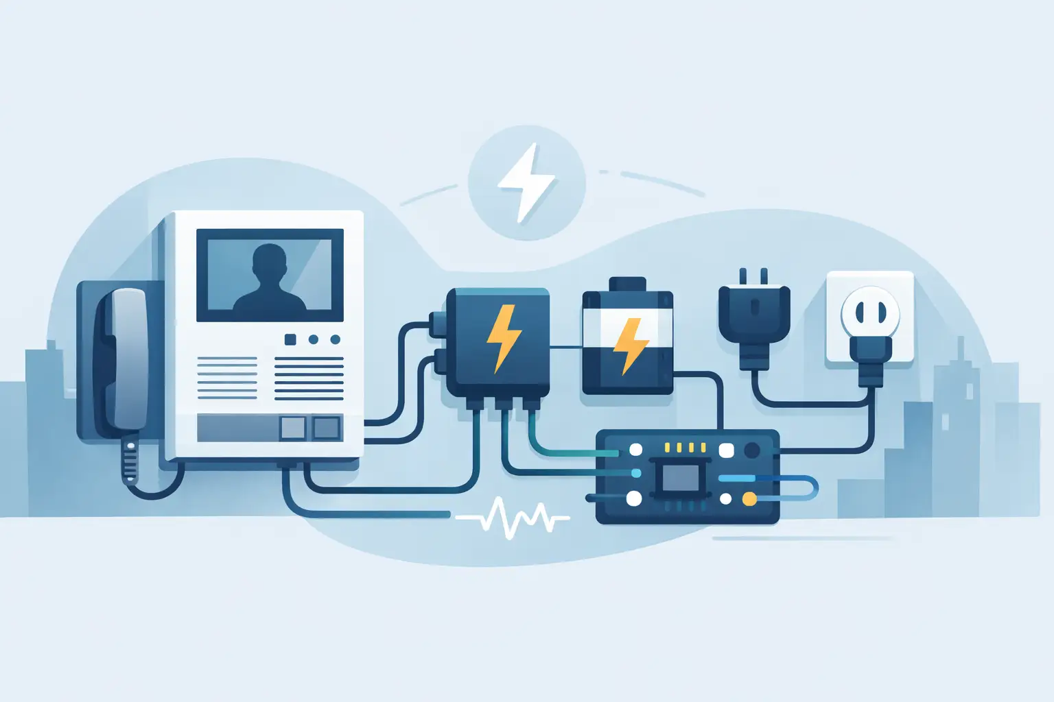
A door station may power up normally on the bench and still fail at the opening when a strike releases, a camera switches to night mode, or a gate operator starts moving. That is why intercom power requirements must be planned as a system calculation, not treated as an accessory purchase. The power supply, wire run, lock type, network equipment, and backup method all affect whether an entry system performs reliably.
For installers and property managers, the objective is straightforward: provide the required voltage at every device under its highest expected load, with enough reserve capacity to handle normal operation, activation events, and future service needs.
Start With the Intercom System Architecture
Before selecting a transformer, DC supply, or PoE switch, identify the type of intercom being installed. A basic single-door audio intercom has very different demands from a multi-tenant video system with indoor monitors, access readers, electric locking hardware, and mobile-app connectivity.
Conventional analog intercoms commonly use low-voltage AC or DC power, often 12V, 16VAC, 18VAC, or 24VDC depending on the manufacturer. Some systems use a dedicated controller power supply and distribute power and communication over separate conductors. Others use a two-wire bus that carries both data and power.
IP video intercoms may be powered through Power over Ethernet (PoE), a local DC supply, or both. PoE can simplify a door-station installation because a single rated network cable carries communication and power. It does not automatically power the lock, however. In many access-control installations, the intercom, controller, and electric lock need separate power planning even when they work together operationally.
Always use the manufacturer’s stated voltage range and power method. A device labeled 12VDC should not be assumed compatible with 12VAC. Likewise, a door station that accepts PoE may require a specific PoE class or standard. Voltage type, polarity, current capacity, and terminal assignment are all installation-critical details.
Intercom Power Requirements: Voltage, Current, and Headroom
Voltage tells you what the equipment expects. Current, measured in amps or milliamps, tells you how much power it consumes. The supply must match the required voltage and provide at least the total current needed by all connected equipment.
A useful starting point is to add the maximum current draw of every component powered by the same supply. Include the door station, master station or monitors if applicable, controller, card reader, request-to-exit device, annunciator, and locking hardware. Then add capacity for peak or inrush current, especially for electric strikes, magnetic locks, motorized locks, and gate-related equipment.
Do not size a supply only to the calculated minimum. A practical allowance is typically 20% to 30% above the expected maximum continuous load, with additional consideration for devices that have documented surge or startup demand. This reserve reduces heat stress, helps maintain voltage at the equipment, and leaves room for a future reader, camera, or second door release.
For example, a 12VDC video door station drawing 500 mA, a reader drawing 120 mA, and a 12VDC electric strike drawing 700 mA need at least 1.32 amps while the strike is energized. A 12VDC, 2-amp supply may be appropriate if the cable distance and other loads are within limits. A 1.5-amp supply is technically close, but it leaves little margin for real conditions.
The lock deserves special attention. Some electric strikes are intermittent-duty devices intended to energize only during a short release period. Others are continuous-duty. Fail-safe magnetic locks are usually energized continuously, while fail-secure strikes may consume power only when a release is requested. The operational choice affects both power-supply sizing and battery-backup expectations.
Calculate Voltage Drop Before Pulling Wire
A correctly sized power supply cannot overcome undersized cable on a long run. As wire distance increases, resistance causes voltage drop. The device at the far end receives less voltage than the output measured at the enclosure.
This is one of the most common causes of unreliable door release. An electric strike may buzz, fail to pull in, or work only when the system is cool and lightly loaded. A video intercom may reboot when its infrared LEDs activate at night. These symptoms can look like defective equipment when the actual problem is voltage arriving below the operating threshold.
Voltage drop depends on conductor gauge, one-way distance, current draw, and the fact that DC circuits travel out and back. The round-trip cable length is what matters. Larger conductors have less resistance and are generally the better choice for locks and long-distance DC power runs.
Use the manufacturer’s distance chart when one is available. For field planning, confirm the voltage at the device terminals while the lock is energized or the intercom is under its highest load. A meter reading taken only at the power supply does not verify field performance.
There is no universal wire gauge for every intercom installation. Short low-current communication runs may work properly on smaller conductors, while a 12VDC strike at a distant gate may require heavier cable, a local power supply, or a higher-voltage distribution approach approved by the equipment manufacturer. Avoid sharing undersized conductors between sensitive electronics and a high-current lock unless the system documentation specifically supports that arrangement.
Separate Lock Power From Communication Power When Needed
Many door intercom problems start when the installer attempts to power the station and locking device from the same small supply. This may work on a light-duty single-door system, but it can introduce voltage sag, noise, ground-reference issues, or momentary intercom resets when the lock activates.
Using a dedicated access-control power supply for locks and control hardware is often the cleaner design. The intercom can be powered according to its own requirements, while its relay output sends a dry contact command to the lock circuit. This arrangement makes troubleshooting easier and gives the lock circuit appropriate fusing, battery charging, and distribution options.
Dry contacts do not provide power. They simply open or close a circuit. If an intercom relay is rated for a particular voltage and current, verify that the connected lock circuit stays within those ratings. For larger loads, use an appropriately rated relay or interface rather than routing power through a door station relay beyond its listed capacity.
PoE Intercoms Need a PoE Budget, Not Just a Network Port
PoE is convenient, but a network switch must have sufficient per-port and total power capacity. A switch may have eight PoE ports but not enough wattage to supply every connected camera, intercom, and access device at maximum demand.
Check whether the door station requires IEEE 802.3af, 802.3at, or another power standard. Also account for cable quality and distance. Ethernet channel length is generally limited to 100 meters, and available power at the device can be affected by cable resistance and the quality of terminations.
A PoE intercom is not necessarily a PoE lock solution. Most electric strikes, maglocks, and gate-control interfaces should receive power from a properly designed lock supply unless the manufacturer specifically provides a rated PoE-powered access-control architecture. Keeping lock power separate also prevents a switch restart from unexpectedly changing door behavior.
Plan Backup Power Around the Site’s Security Expectations
Battery backup is not required for every intercom application, but it should be considered wherever entry control must remain operational through brief utility outages. Apartment entries, commercial exterior doors, schools, healthcare sites, and managed gates often have stronger continuity requirements than a basic private residence.
A battery-backed DC power supply can maintain power to controllers, door stations, readers, and compatible locks. Runtime depends on the battery amp-hour rating and the actual load. Continuous loads such as magnetic locks reduce runtime much faster than momentary-release strikes.
Power-loss behavior must be selected intentionally. A fail-safe maglock unlocks when power is removed, which may be appropriate for life-safety egress but may not meet the desired security condition during an outage. A fail-secure strike generally remains locked without power, but authorized entry may be unavailable until power returns. Local codes, fire-alarm interface requirements, door hardware, and occupancy use all matter here.
For any electrified egress door, coordinate the intercom design with applicable building, fire, and life-safety requirements. An intercom relay should never be treated as a substitute for correctly designed egress hardware or required emergency release functions.
Common Power Mistakes That Create Service Calls
Most avoidable failures come from a few field decisions: using AC where DC is required, selecting a supply with no current reserve, placing a long-run lock on small gauge wire, assuming a relay output powers the lock, or overlooking the combined PoE budget of a network switch.
Another frequent issue is placing power equipment where it cannot be serviced. A listed, enclosed power supply installed in an accessible and protected location is easier to inspect, test, replace, and connect to backup batteries. Label outputs by door and keep a current record of voltage, fuse rating, lock type, and cable route. Those details shorten future troubleshooting considerably.
For multi-door or multi-tenant work, standardize the power design before the first device is installed. Separate circuits, correctly rated distribution boards, clear fuse protection, and documented load calculations are less expensive than diagnosing intermittent releases after occupancy.
A dependable intercom installation starts with the door condition and works backward: determine how the door must behave, select compatible lock and intercom equipment, calculate the real load at the farthest device, and then choose the power method. When the application is unusual, verify the design before ordering equipment. The right supply and wire plan are small parts of the project, but they determine whether the system is ready when someone presses the call button.

 No products in the cart.