
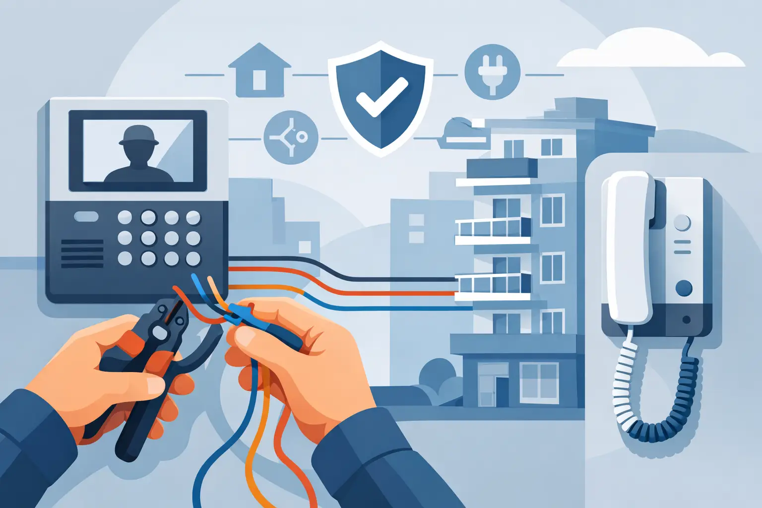
A failed apartment intercom is rarely caused by the master station alone. More often, the problem is in the pathway: an unmarked splice, an undersized power supply, a shared cable with the wrong conductor count, or a door release that was never matched to the access-control hardware. Knowing how to wire apartment intercom equipment starts with treating it as a building system, not a single device.
For a small two-unit building, the work may be straightforward. For a larger multifamily property with multiple entrances, electric locks, postal locks, cameras, and tenant stations, the wiring plan needs to be established before cable is pulled. A clean design reduces callbacks, makes service practical, and leaves room for future replacement parts or system upgrades.
Start With the Intercom Architecture
Apartment intercom systems are not wired one universal way. The manufacturer’s wiring diagram always controls because terminal names, voltage requirements, conductor counts, and maximum distances vary by system. Before selecting cable, identify which architecture the building will use.
Traditional analog intercoms use dedicated conductors between the entrance panel, tenant stations, power supply, and door strike or magnetic lock. These are common in older walk-up buildings and can be economical when the cable routes are accessible. Depending on the model, each apartment may need its own call wire plus common conductors, or the system may use a multi-wire configuration with shared audio and control lines.
Bus-based systems reduce the amount of field wiring by placing many stations on a common two-wire or multi-wire bus. They can simplify riser wiring in larger buildings, but polarity, branch limits, termination requirements, and approved cable types matter. A bus system can save labor, yet troubleshooting is more dependent on following the manufacturer’s layout rules exactly.
IP intercom systems use structured network cabling, typically Cat5e or Cat6, and may receive power through Power over Ethernet. They are a strong option where the property needs video calling, mobile credentials, remote management, or integration with networked access control. They also require a properly designed network, switch capacity, surge protection, and a plan for what happens when network equipment loses power.
Build the Wiring Plan Before Pulling Cable
Create a riser diagram that shows every component and every cable route. At minimum, document the entrance station location, apartment stations, equipment room, power supplies, door hardware, exit devices, network switch if used, and any secondary entrances. Label units consistently. Unit 2B should be 2B on the entrance directory, cable tags, station label, and as-built drawing.
Measure actual cable paths rather than estimating from a floor plan. Vertical risers, fire-rated pathways, masonry walls, and long runs to detached entrances can change the installation significantly. Cable length affects voltage drop, audio quality, data performance, and lock operation.
Keep low-voltage intercom conductors separated from line-voltage wiring. Where the cables must cross, cross at 90 degrees when possible. Do not use an old, unidentified cable just because it is already in the wall. It may have damaged insulation, too few conductors, unsuitable gauge, or an unknown path that makes future service difficult.
For a professional installation, label both ends of every field cable before termination. Leave reasonable service loops at the entrance panel, tenant stations, control enclosure, and power supply. These small details are what allow an installer to isolate a bad unit without opening every apartment.
Select Cable and Power for the System
Cable selection is driven by the intercom manufacturer, distance, environment, and device type. Use the specified conductor count and gauge for analog audio stations. Shielded cable may be required where electrical interference is likely, while some systems specifically require unshielded cable. For IP stations, use solid copper, rated network cable rather than copper-clad aluminum cable.
Door hardware deserves its own circuit planning. An electric strike, electric latch retraction device, or maglock can draw substantially more current than the intercom’s communication circuit. Do not assume the intercom power supply can operate the door lock. Many installations use a separate, properly sized, listed power supply for locking hardware, with the intercom providing only a dry contact or relay output.
Calculate lock current using the device’s operating rating, then account for wire length and voltage drop. A strike that works on the bench but chatters at the door usually points to inadequate voltage at the lock, a poor splice, incorrect wire gauge, or a power supply that cannot handle the load. Continuous-duty devices, especially magnetic locks, require careful power and backup planning.
Use listed power supplies and follow local code requirements for enclosures, overcurrent protection, battery backup, and fire alarm interface. Work involving branch-circuit power, fire alarm systems, egress hardware, or electrified locking should be performed or reviewed by qualified licensed professionals as required in the jurisdiction.
How to Wire Apartment Intercom Components
Once the pathways and equipment are confirmed, install the system in logical sections. Mount the entrance panel at the specified height and protect its cable entry from weather and tampering. Outdoor stations should have a weather-rated back box or enclosure, sealed conduit entries where required, and drip management so water cannot follow cable into the equipment.
Run the main riser from the equipment location to the entrance panel or distribution point. Then run individual home runs or approved branch runs to each tenant station, following the selected system architecture. Avoid hidden splices. If a splice is unavoidable, place it in an accessible, properly rated junction enclosure and document it.
At each tenant station, terminate conductors only after confirming the unit number and station address. Analog systems may use terminals for common, speaker, microphone, call, and door release. Bus systems may use only a pair of bus terminals plus an address setting. IP systems typically use one Ethernet connection, but the network configuration, device address, and call directory must still be programmed.
Wire the entrance panel’s door-release relay according to the lock circuit design. In many cases, the relay switches power to the strike or controls a separate access-control relay. Confirm whether the hardware is fail-secure or fail-safe before wiring it:
- A fail-secure electric strike stays locked when power is removed and is common where the door must remain secured during a power outage.
- A fail-safe magnetic lock releases when power is removed and is commonly used where life-safety and code requirements call for release on loss of power.
This choice affects relay logic, emergency release devices, fire alarm release, backup power, and local code compliance. Do not use an intercom door button as the only consideration in an electrified opening. The entire opening must function correctly for authorized entry, free egress, emergency release, and fire alarm operation where applicable.
Test in Stages, Not After Every Wall Is Closed
Test cable runs before installing finished trim. Check continuity, conductor identification, shorts to other conductors, and shorts to ground where applicable. For networked systems, certify or at least test each network run with appropriate equipment before connecting stations.
Power up one section at a time. Confirm correct voltage at the power supply and again at the far-end device under load. Then verify calling, two-way audio, video where included, tenant station operation, entrance-panel directory selection, and door release. Test the lock while the door is physically closed and while the system is drawing normal load.
Audio problems should be diagnosed methodically. Hum or noise can result from cable routing near power, grounding issues, incorrect shielding practices, or a defective station. Weak audio may come from excessive distance, low voltage, loose terminals, moisture intrusion, or an improperly adjusted entrance panel. Replacing components before checking the cable and voltage usually wastes time.
For buildings with several apartments, test every station individually and test simultaneous-use behavior if the system supports it. Verify that Unit 1 does not call Unit 2, that one apartment’s door-release command cannot activate another entrance, and that directory programming matches the installed units.
Common Apartment Intercom Wiring Mistakes
The most expensive mistakes occur before commissioning. Mixing cable types without documenting them, daisy-chaining stations on a system that requires home runs, placing power supplies in inaccessible locations, and undersizing lock wiring all create avoidable service issues.
Another common problem is treating the intercom, lock, and exit hardware as separate projects. They are connected at the door. A properly installed system accounts for the door condition, strike alignment, latch type, request-to-exit device, fire alarm requirements, and the power available at that opening.
When replacing an existing apartment intercom, identify the old system type before ordering equipment. A new station is not automatically compatible with an existing entrance panel, and an older multi-wire system may not convert to a two-wire or IP system without replacing more of the infrastructure. Compatibility should be confirmed at the system level, not assumed from the appearance of a handset.
A well-wired apartment intercom should be easy to service years after installation: labeled cables, accessible power, documented terminals, dependable door release, and a design that matches the building’s actual needs. That is the standard worth planning for before the first cable enters the wall.

 No products in the cart.