
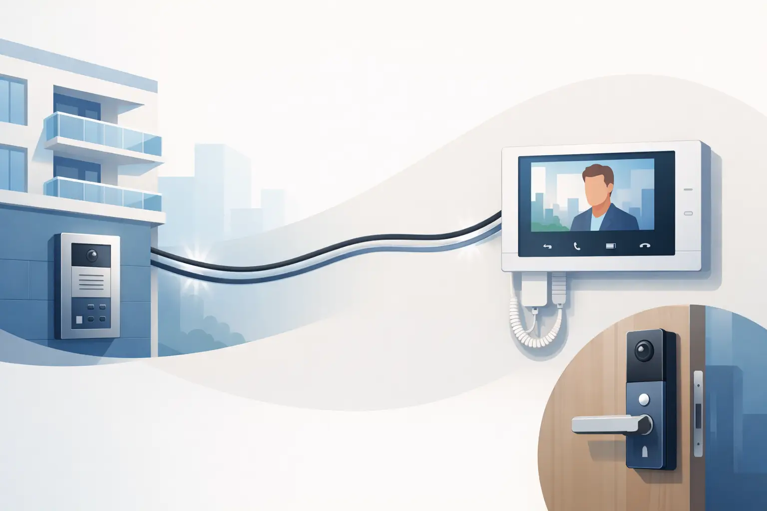
A 2 wire building intercom setup is often the most practical way to add visitor communication and controlled entry to an occupied property without opening every wall for new cable. That benefit is real, but it does not mean every two-conductor cable already in a building is ready for an intercom system. The system architecture, cable condition, station count, lock requirements, and distance limits all need to be verified before equipment is selected.
For apartment buildings, offices, schools, mixed-use properties, and gated facilities, the goal is not simply to make a call from a door station to an indoor monitor. The system must give staff or residents reliable communication, release the correct door, tolerate daily use, and remain serviceable when a station or power supply needs attention.
Start the 2 Wire Building Intercom Setup With a Site Plan
The first decision is what the intercom needs to control. A single front entrance serving a small office has very different requirements from a multifamily building with dozens of tenant stations, a vehicle gate, a rear service door, and a management office.
Document each entry point, the number of indoor stations, and the locations where users need to answer calls. Include existing locks, request-to-exit devices, fire alarm interfaces, access-control readers, and any camera coverage already in place. A door station may need to work alongside a keypad, card reader, or mobile credential system rather than replace it.
Also identify the calling method. In a residence, visitors may select a unit from a directory and press a call button. In a small commercial site, a single call button to reception may be enough. At a school or industrial facility, the preferred workflow may be a call to a staffed office before a door is released. These operational details determine whether the project needs a multi-button panel, directory station, video master station, guard station, or a combination of equipment.
A basic site plan should confirm four items before ordering:
- Number and type of entrance panels
- Number of tenant, office, or master stations
- Existing cable routes and approximate distances
- Door hardware and power requirements at every controlled opening
This information prevents a common problem: buying an intercom package that handles communication but cannot properly operate the installed locking hardware.
Understand What “2 Wire” Means for the System
A two-wire intercom generally uses a dedicated two-conductor bus to carry system communication and, depending on the product family, power and video. This can significantly reduce installation labor compared with systems that require separate runs for network data, power, audio, video, and control.
However, two-wire systems are not universally interchangeable. Many use manufacturer-specific communication methods, power supplies, distributors, and programming procedures. An entrance station from one platform may not communicate with indoor stations from another, even when both are described as two-wire products.
Cable type matters as well. Existing low-voltage cable can sometimes be reused, particularly on retrofit projects, but suitability depends on conductor gauge, total run length, splices, moisture exposure, and electrical noise. Old unshielded cable may work well on a short interior run and perform poorly when routed beside motors, fluorescent ballasts, or high-voltage feeders. A cable test and visual inspection are less expensive than troubleshooting intermittent calls after installation.
Do not assume that the intercom bus can directly power a door strike, maglock, gate operator, or high-current latch. The intercom relay usually provides a dry contact or low-current switching output. The locking device often requires a separate, properly sized power supply and the correct relay wiring. This distinction is especially important with maglocks, which can draw substantial current and must be tied into life-safety and egress requirements.
Choose Equipment Around the Building’s Daily Workflow
A complete installation typically includes an entrance station, indoor stations or answering devices, a system power supply, bus distribution hardware, and door-release integration. Video systems add cameras at the entrance and monitors or video-capable indoor stations. Some projects also use a desktop guard station, secondary door station, or app-capable interface where the selected platform supports it.
For a small office, a single video door station and one or two master monitors may be sufficient. The value is clear: staff can verify a visitor before releasing the door, while the electric strike remains connected to an existing access-control schedule or request-to-exit device.
For a multifamily property, capacity and expansion deserve more attention. Confirm the maximum number of stations, supported entrances, directory options, and available distribution modules. A building with 24 units may only need 24 stations now, but leaving capacity for a leasing office, package room, rear entrance, or future unit conversion can avoid replacing core equipment later.
Facilities with multiple doors should also establish release permissions. A person answering a call from the front entrance should not automatically be able to release a loading dock or restricted staff door. The intercom must be configured so each station has appropriate call and release authority.
Plan Cable Routes, Power, and Door Hardware Together
The best intercom design can fail at the door if field wiring and lock selection are treated as separate jobs. Plan the entrance station cable, lock power, relay connection, door position switch, request-to-exit device, and fire alarm release path as one opening-specific package.
An electric strike is often a straightforward choice for a latched door because it allows the mechanical door hardware to remain locked while the strike releases electronically. A maglock may fit glass doors, aluminum storefronts, or certain commercial openings, but it requires careful attention to code-compliant egress, emergency release, and backup power. Electrified panic hardware, cabinet locks, gate operators, and delayed-egress systems bring their own application requirements.
Voltage drop is another field issue. Long runs to a lock can leave a device underpowered at the moment it is asked to release. Use the lock manufacturer’s voltage and current requirements to size conductors and power supplies. If the lock is a fail-safe device, confirm what should happen during a power loss. If it is fail-secure, verify that the exit path remains compliant and practical for occupants.
Keep low-voltage intercom cable separated from line-voltage wiring whenever possible. Use suitable pathways, protect cable at penetrations, label both ends, and leave enough service loop for replacement or termination work. In older buildings, clearly labeling the bus, lock power, and relay conductors saves significant time for future maintenance teams.
Install in Logical Stages
A staged installation reduces avoidable problems. First, mount and wire the entrance station and indoor stations according to the system topology. Some platforms use a daisy chain, while others require star distribution modules or specific branch limits. Following the manufacturer’s topology is not optional – an improvised layout can cause power loss, missed calls, or unstable video.
Next, install the system power supply in an accessible, protected location. Avoid placing it above inaccessible ceilings or inside a crowded electrical enclosure where service work is difficult. If battery backup is required, use a power arrangement designed for the load and test actual runtime rather than assuming a battery will support every component equally.
Then wire the door-release relay and lock power. Before connecting the intercom relay, verify the lock independently with its intended power supply, request-to-exit device, and door hardware. This confirms that the opening latches correctly, releases correctly, and does not bind mechanically. An intercom cannot compensate for a poorly aligned strike or a door that needs excessive force to open.
After the physical installation, program station addresses, unit names, call routing, unlock timing, and entrance permissions. Keep a written record of station numbers, cable routes, power supply locations, and programming credentials. For managed properties, this documentation is part of the installation, not an extra.
Commission Before Turning the System Over
Testing should cover normal use and failure conditions. Place calls from every entrance to every intended station. Verify audio clarity, video framing where applicable, call volume, door release, and any transfer or guard-station functions. Test one station while another is in use if the property expects simultaneous activity.
At each controlled opening, test the lock under real door pressure. A strike that releases while the door is held closed can behave differently when weather seals, misalignment, or occupant force are involved. Confirm request-to-exit operation, door position monitoring, and any access-control reader operation after the intercom has been added.
Finally, verify what happens after power is cycled. Stations should recover, directory data should remain correct, and locks should return to the intended security state. If the system integrates with fire alarm, emergency release, or building access control, coordinate testing with the responsible installer and authority requirements.
A well-planned two-wire system can make a retrofit far less disruptive while providing professional entry control for years. The practical next step is to match the building layout, cable reality, and door hardware to a compatible system before installation begins – because the right equipment package is easier to install, easier to support, and far more dependable at the door.

 No products in the cart.