
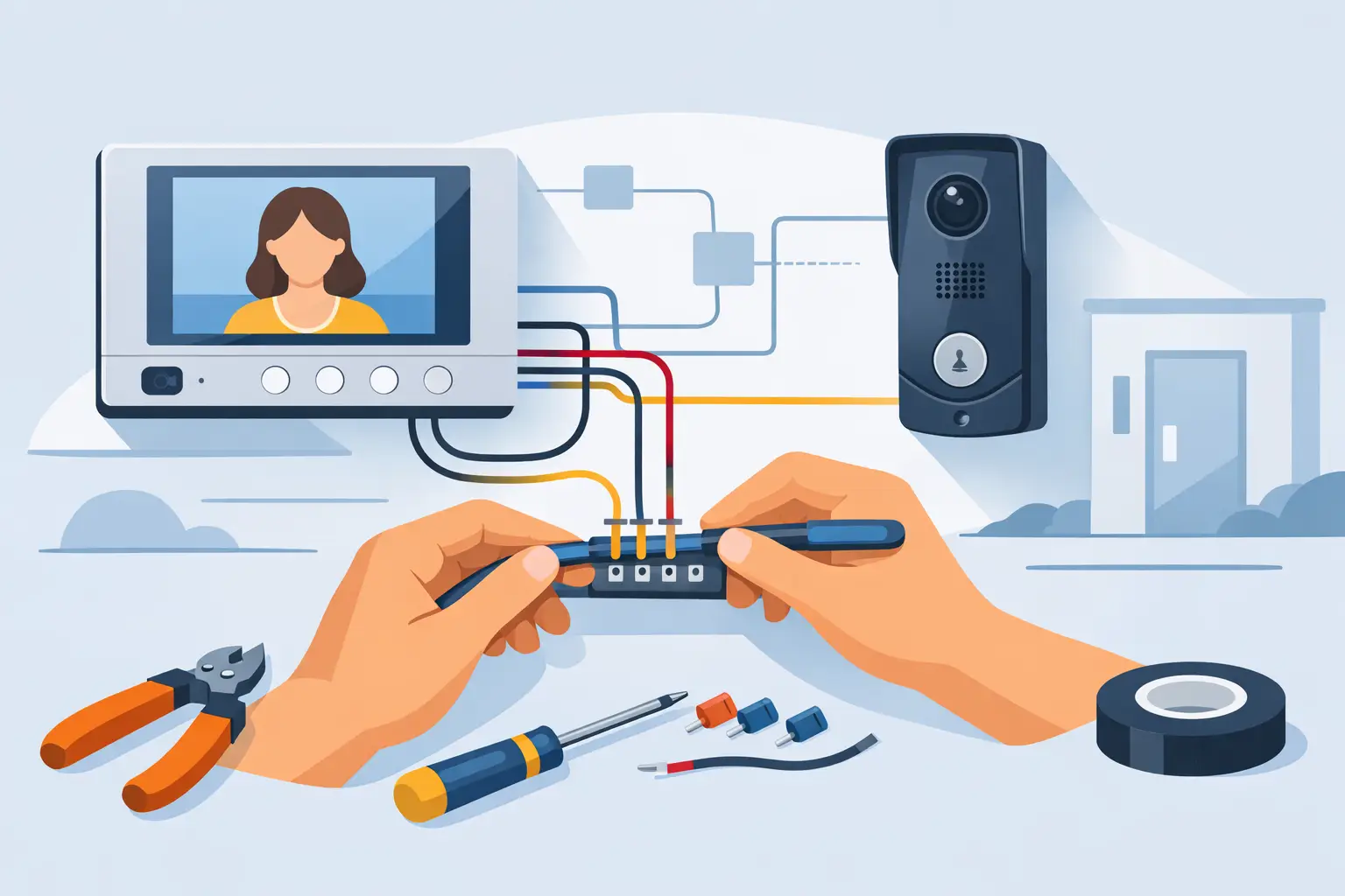
A video intercom installation can look straightforward until the door lock, power supply, cable distance, gate operator, and indoor monitor all need to work together. Knowing how to wire video intercom equipment correctly starts with treating it as an access-control system, not just a doorbell with a camera. The wiring plan must support communication, video, door release, and reliable power under real operating conditions.
For a single-family front door, the system may involve one outdoor station, one indoor monitor, a power supply, and an electric strike. At a commercial entrance or multi-unit building, it may also include multiple monitors, directory panels, card readers, exit devices, request-to-exit hardware, and a separate access-control system. The product manual for the specific system always takes priority, but the planning principles below apply to most professional video intercom installations.
Start With the System Architecture
Before pulling cable, identify every device in the opening system and determine what it needs to do. A typical installation includes an outdoor door station with camera and call button, one or more indoor monitors or master stations, power supplies, a locking device, and the cable path between them. IP systems may also use a network switch, PoE switch, router, or dedicated network connection.
The first decision is whether the intercom is a two-wire, four-wire, multi-conductor analog, or IP-based system. These systems are not interchangeable. A two-wire intercom may carry power, audio, video, and data over a manufacturer-specific bus. A traditional four-wire system may use separate terminals for power, audio, video, and common. An IP video intercom commonly uses Cat5e or Cat6 cable and may receive both data and power through PoE.
Do not assume that a cable type is suitable just because it physically fits a terminal. The manufacturer may specify conductor size, maximum distance, shield requirements, and termination method. Substituting cable without confirming those requirements can cause weak video, intermittent calling, lock-release failures, or damaged equipment.
How to Wire Video Intercom Components
Begin at the outdoor station and work outward from its terminals. Label every cable at both ends before termination. This simple step prevents wasted troubleshooting time when several stations, monitors, or doors are involved.
Wire the Door Station to the Monitor or Network
For a conventional wired system, run the specified intercom cable from the outdoor station to the indoor monitor or system distributor. Keep the wire route protected from weather, vandalism, and physical damage. Exterior cable should be rated for the installation environment, and underground runs should use suitable conduit and cable rated for burial or wet locations.
Terminate each conductor exactly as shown in the wiring diagram. On a multi-wire system, terminal labels may include power positive and negative, audio, video, common, data, or bus connections. On an IP station, terminate the Cat5e or Cat6 cable using the wiring standard required by the device, typically T568B, and connect it to the designated PoE switch or network port.
Avoid running low-voltage intercom cable alongside high-voltage electrical conductors for long distances. Electrical interference can show up as noise in audio, lines in video, unstable communication, or random device resets. If the runs must cross, cross them at a 90-degree angle where practical.
Supply Power the Right Way
Power is where many intercom installations fail. The door station, monitor, and lock may each have different voltage and current requirements. Some systems use a central power supply. Others use a local plug-in transformer, DIN-rail power supply, PoE, or a dedicated lock power supply.
Check whether the intercom power supply is intended to operate the lock. In many cases, it is not. A video monitor may provide a dry relay contact that tells an external power supply to energize or release the lock, but the monitor itself should not be expected to carry the lock load.
Size the power supply for the total connected load, including peak current. Electric strikes, maglocks, gate controls, and illuminated hardware can require more current than the intercom electronics. Allow capacity for voltage drop on long wire runs and for future devices where appropriate. A lock that works at the bench but fails at the door is often dealing with insufficient voltage under load.
Connect the Door Release Relay
Most video intercoms release a door through a relay output. The relay is commonly labeled COM, NO, and NC. COM is the common terminal, NO is normally open, and NC is normally closed. The correct choice depends on the locking hardware and the desired security condition.
An electric strike is often wired through the normally open relay path so power is applied only when a user presses the release button. A magnetic lock is commonly wired through the normally closed path so it remains powered and locked during normal operation, then drops power to unlock. This is a general pattern, not a substitute for the lock manufacturer’s diagram.
Determine whether the opening must be fail secure or fail safe. A fail-secure electric strike stays locked during a power outage and usually requires a key or other mechanical method for entry. A fail-safe maglock unlocks when power is removed, which can be appropriate for life-safety egress but requires careful planning for security and code compliance.
For any electrically controlled opening, maintain free egress. Do not use the intercom release button as the only way out. Commercial openings may require a request-to-exit device, mechanical egress hardware, fire alarm interface, emergency release, or other code-required components. Requirements vary by jurisdiction and occupancy, so confirm the design with the authority having jurisdiction and qualified access-control professionals.
Plan Cable Type and Distance Before Installation
Cable selection depends on the intercom platform, distance, and environment. Cat5e or Cat6 is standard for many IP stations and PoE devices. Shielded cable can be helpful in electrically noisy locations when the manufacturer permits or requires it. Traditional analog and proprietary systems may need multi-conductor cable with a specific gauge.
Distance matters as much as cable type. Video intercom manufacturers publish maximum cable lengths, often with different limits based on conductor size, the number of monitors, and whether the cable also carries power. A long driveway gate is a common example: communication may work while the electric strike or gate-release relay behaves inconsistently because the power circuit has too much voltage drop.
When a gate station is far from the building, consider a local power supply in a protected enclosure if allowed by the system design. Use surge protection where appropriate, especially for outdoor stations, gate equipment, and cable runs between separate buildings. Grounding and bonding should follow equipment instructions and applicable electrical requirements.
Keep the Lock Circuit Separate When Needed
A professional installation often separates the intercom circuit from the lock power circuit. The intercom’s relay then acts as a control switch, while a dedicated power supply delivers the current required by the strike, maglock, or gate relay.
This arrangement reduces the chance that lock current will pull down the monitor or door station. It also makes troubleshooting cleaner. If the monitor communicates normally but the door will not release, technicians can test the relay output, lock power supply, cable run, and locking device as separate parts of the system.
Where the intercom controls a gate operator, use the operator’s designated low-voltage trigger input rather than trying to power the motor circuit through the intercom. The intercom relay should mimic a momentary push button or dry-contact command specified by the gate operator manufacturer.
Test Before Closing Walls or Mounting Covers
Test the installation in stages. First, confirm voltage at the equipment terminals with a meter. Then verify the door station boots, calls the correct monitor, provides clear two-way audio, and delivers usable video in both daylight and low light. Test every monitor if the system has more than one.
Next, test the door-release function while measuring voltage at the lock. Watch for a large voltage drop when the lock is energized. Confirm the strike releases without binding and that a maglock holds with the expected force. Mechanical alignment matters: a perfectly wired strike can still fail if the door, latch, or gate is misaligned.
For commercial and managed properties, test the system during normal site conditions. A gate release should work when vehicles are arriving, a lobby station should be audible in a busy office, and a multi-unit panel should call the correct tenant. Document cable routes, power supply locations, terminal assignments, and device addresses for future service.
Common Wiring Problems to Avoid
The most frequent issues are usually predictable: using undersized cable on long runs, powering locks from an intercom output not rated for the load, reversing polarity, mixing incompatible system components, and omitting surge protection at outdoor stations. Another common mistake is leaving no service loop at the door station or monitor, making future replacement more difficult than necessary.
Do not energize a system until all exposed conductors are checked for shorts and all terminal screws are secure. If line voltage is present near the installation, keep that work separate from low-voltage intercom wiring and use a licensed electrician where required. Access-control and egress requirements deserve the same level of attention as the camera and monitor.
The best video intercom installation is one that remains serviceable after the first call is answered. A clear wiring diagram, correctly sized power, labeled cables, and hardware matched to the opening will save far more time than a rushed termination at the door.

 No products in the cart.